RaspIR
I can now turn my lights on and off from my phone
Short update to keep this half-working with Linux Kernel 4.19 here
I forget exactly what drove me to do this, probably sheer laziness; I was getting tired of getting out of bed to turn the lights in my bedroom on and off. In the age of the smartphone and internet of things, it seemed obvious to try some sort of internet-enabled solution, just in case I was ever on the other side of the planet and wanted to turn my lights on. Looking around online it seemed that the only out-of-the-box solutions were either prohibitively expensive and/or required bulbs controlled through a wifi-connected RF base station. Besides, doing that kind of thing would really damage what little hacker cred I have to begin with.
Then it occurred to me that with a cheap (~£10) IR-controlled lightbulb and some IR LEDs, I could probably hack something together using a Raspberry Pi. Thankfully, I already had one of those lying around (it sits on my desk and wakes my desktop up when I throw TCP packets at it).
An additional bonus was that it gave me an excuse to try out Flutter, Google’s new app development framework for Android and iOS.
Before I begin, I have to disclose that large parts of this were informed by a tutorial on alexba.in. Without that tutorial I probably would never have managed this.
I’ve been meaning to write this up for a while now, mainly just as a reminder to myself on how I glued everything together!
Parts #
Electronics-wise this is quite a simple project:
- Infrared LEDs (I used two, because why not)
- 10kΩ resistor
- NPN transistor (e.g. 2N2222)
- TSOP38238 Infrared Receiver
Discounting minimum quantities, I think that amounts to about £0.70 in parts. The PCBs I had fabbed (more on that later) cost more than that.
LIRC #
The actual sending and receiving of IR data is performed with LIRC, a Linux package, installed on the Raspberry Pi with:
sudo apt-get install lirc
We then have to tell LIRC which pins to use for sending and receiving data.
Add the following to /etc/modules:
lirc_dev
lirc_rpi gpio_in_pin=17 gpio_out_pin=27
And add the following to /boot/config.txt:
dtoverlay=lirc-rpi,gpio_in_pin=17,gpio_out_pin=27
Finally, modify /etc/lirc/lirc_options.conf:
driver = default
The Circuits #
Below is the basic circuit diagram.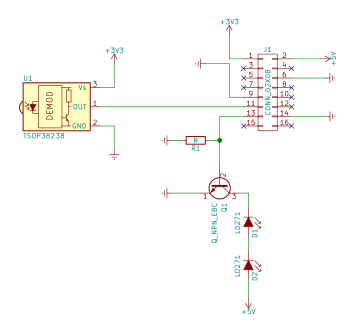
This was all assembled on a breadboard that lived on my desk, with jumper cables galore. Sadly, I have no pictures of the monstrosity.
KiCad #
Eventually, I grew tired of the rat’s nest of wires sat on my desk and set about designing a two-layer PCB to replace it, which I designed in KiCad.
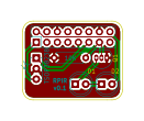
I’m impressed with KiCad; for someone who before this had never really done any PCB design, this was pretty painless, finding footprints for each part was probably the most irritating bit.
The board measures less than an inch square, 0.95" x 0.75". Originally I was going to use a full length 2x20 connector for the Raspberry Pi, but the overall footprint of these parts was so small that it simply wasn’t worth the extra cost of fabbing a board that size, hence the 2x8.
I sent these plans to OSH Park and got three copies of the board for $3.60 with free postage. Nice purple boards, bit of a wait but for a hobbyist who just wants a couple of copies to mess about with, it doesn’t really matter.
Here’s a glamour shot of the board: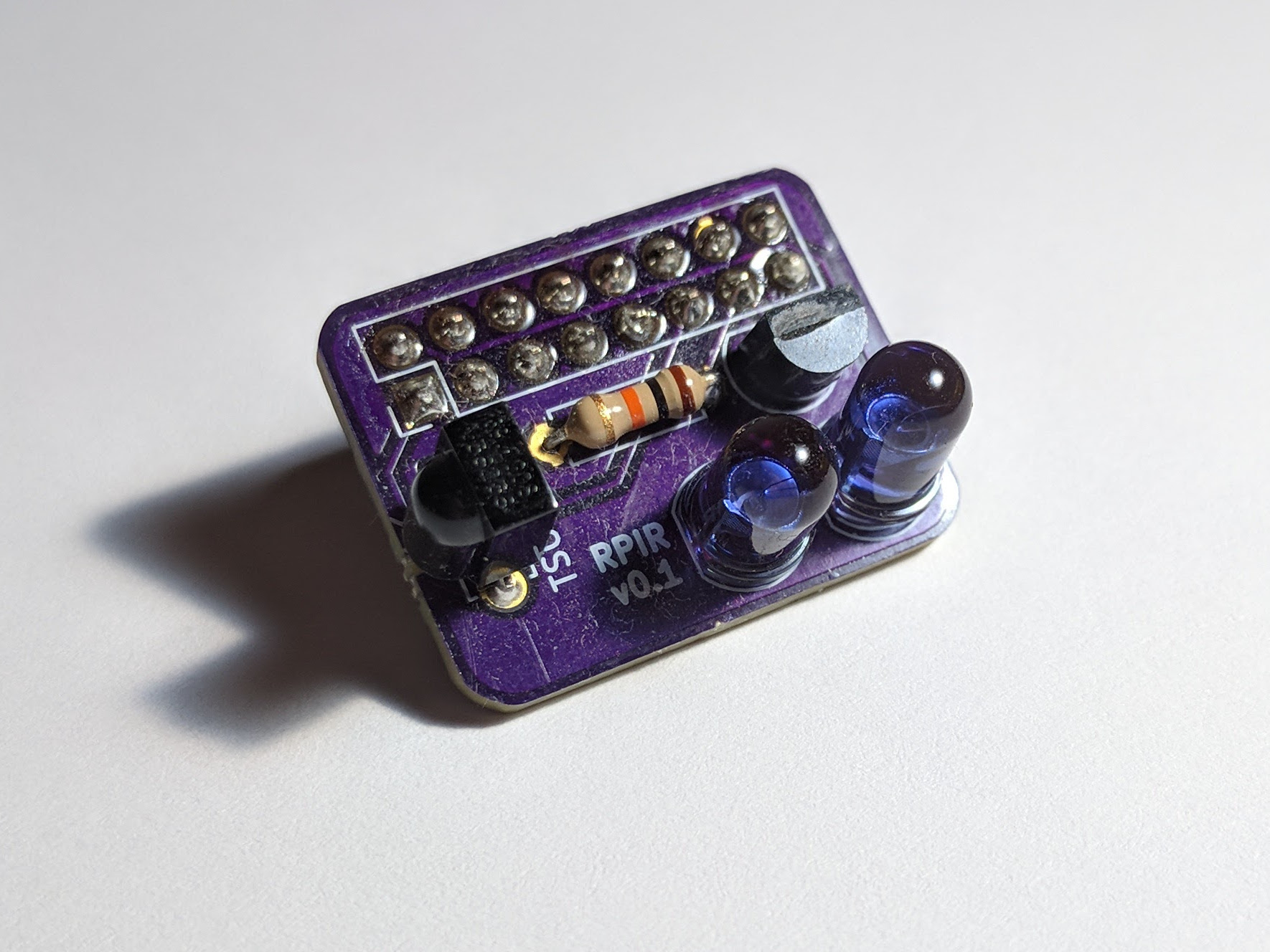
And attached to the Raspberry Pi for scale: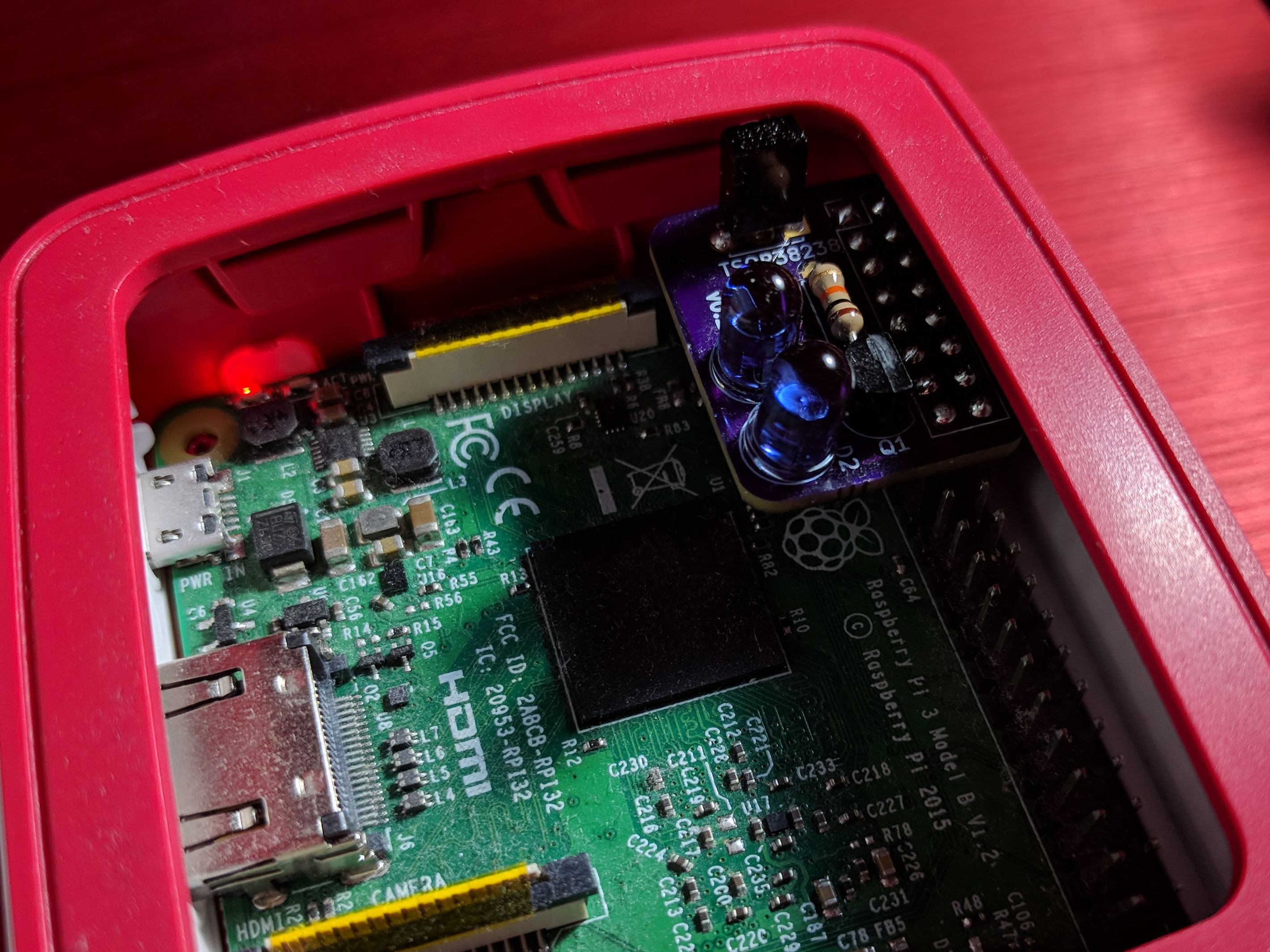
Learning IR Codes #
Even this was quite simple.
sudo irrecord -d /dev/lirc0 /etc/lirc/lircd.conf.d/my_remote.conf
And follow the instructions on screen to learn each of the buttons on your remote.
Then if you take a peek at /etc/lirc/lircd.conf.d/my_remote.conf:
alecks@rp3>  cat /etc/lirc/lircd.conf.d/my_remote.conf

# Please make this file available to others
# by sending it to <[email protected]>
#
# this config file was automatically generated
# using lirc-0.9.0-pre1(default) on Tue Jul 25 20:14:01 2017
#
# contributed by
#
# brand:
# model no. of remote control:
# devices being controlled by this remote:
#

begin remote

  name  AURAGLOW
  bits           16
  flags SPACE_ENC|CONST_LENGTH
  eps            30
  aeps          100

  header       9067  4477
  one           579  1660
  zero          579   555
  ptrail        579
  repeat       9070  2212
  pre_data_bits   16
  pre_data       0xF7
  gap          107975
  toggle_bit_mask 0x0

      begin codes
          brightness_up            0x00FF
          brightness_down          0x807F
          off                      0x40BF
          on                       0xC03F
          red                      0x20DF
          green                    0xA05F
          blue                     0x609F
          white                    0xE01F
          r1                       0x10EF
          g1                       0x906F
          b1                       0x50AF
          flash                    0xD02F
          r2                       0x30CF
          g2                       0xB04F
          b2                       0x708F
          r3                       0x08F7
          b3                       0x8877
          b3                       0x48B7
          g3                       0x8877
          r4                       0x28D7
          g4                       0xA857
          b4                       0x6897
          strobe                   0xF00F
          fade                     0xC837
          smooth                   0xE817
      end codes

end remote
The brand of this particular remote controlled bulb is “Auraglow”, by the way. It’s got lots of pretty colours and strobey functions.
You can test each of the buttons with:
irsend SEND_ONCE <REMOTE_NAME> <CODE>
For example, in my case:
irsend SEND_ONCE AURAGLOW red
Sets the lights to red.
Controlling over the network #
The next thing I wanted to be able to do was to trigger the sending of these IR signals remotely. There’s probably a simpler way of doing this, but I chose good old Python.
import socket
import sys
import re #Added in edit, see below
from subprocess import call

UDP_PORT = 5006
UDP_IP = "0.0.0.0"

if len(sys.argv) > 0:
  UDP_PORT = int(sys.argv[1])

sock = socket.socket(socket.AF_INET,socket.SOCK_DGRAM) # Internet,UDP
sock.bind((UDP_IP, UDP_PORT))

print("Listening on : "+str(UDP_IP)+":"+str(UDP_PORT)+"...")

while True:
  data = b''
  addr = ""
  data, addr = sock.recvfrom(1024)

  print("received message: ", data, " from: ", addr)
  print("length: ", len(data))
  print("decode: ", data.decode())

  m = data.decode()
  m = re.split("[^a-zA-Z0-9 _]", m)[0] #Edit: This line prevents shell injection!
  call("irsend SEND_ONCE " + m,shell=True)
Code also available in this github repo.
This script listens on UDP port 5006 for a string that it can tack onto the end of irsend SEND_ONCE to form a command. So I just send AURAGLOW strobe to that port and it’s time for a rave.
Is it secure? Probably not. But it works. Remember, this is being driven by laziness.
Edit: It’s definitely not secure, like ‘vulnerable to shell injection’ not secure. Since we need shell=True in the call command, we have to do some input sanitisation instead. I don’t think this is necessarily best practice (i.e. I think best practice would be to quote the command, but I couldn’t get that to work).
Adding this line: m = re.split("[^a-zA-Z0-9 _]", m)[0] (the second to last one) stops any funny business.
Set this is run at boot with a systemd service file, /etc/systemd/system/lirclistener.service:
[Unit]
Description=Python script processing lirc requests
Want=network.target
After=network.target

[Service]
User=root
Group=root
WorkingDirectory=/home/alecks/git/lircListener
ExecStart=/usr/bin/python3 lircListener.py 5006
Restart=always
RestartSec=5

[Install]
WantedBy=multi-user.target
And then enable and start it with:
sudo systemctl enable lirclistener.service
sudo systemctl start lirclistener.service
Android App #
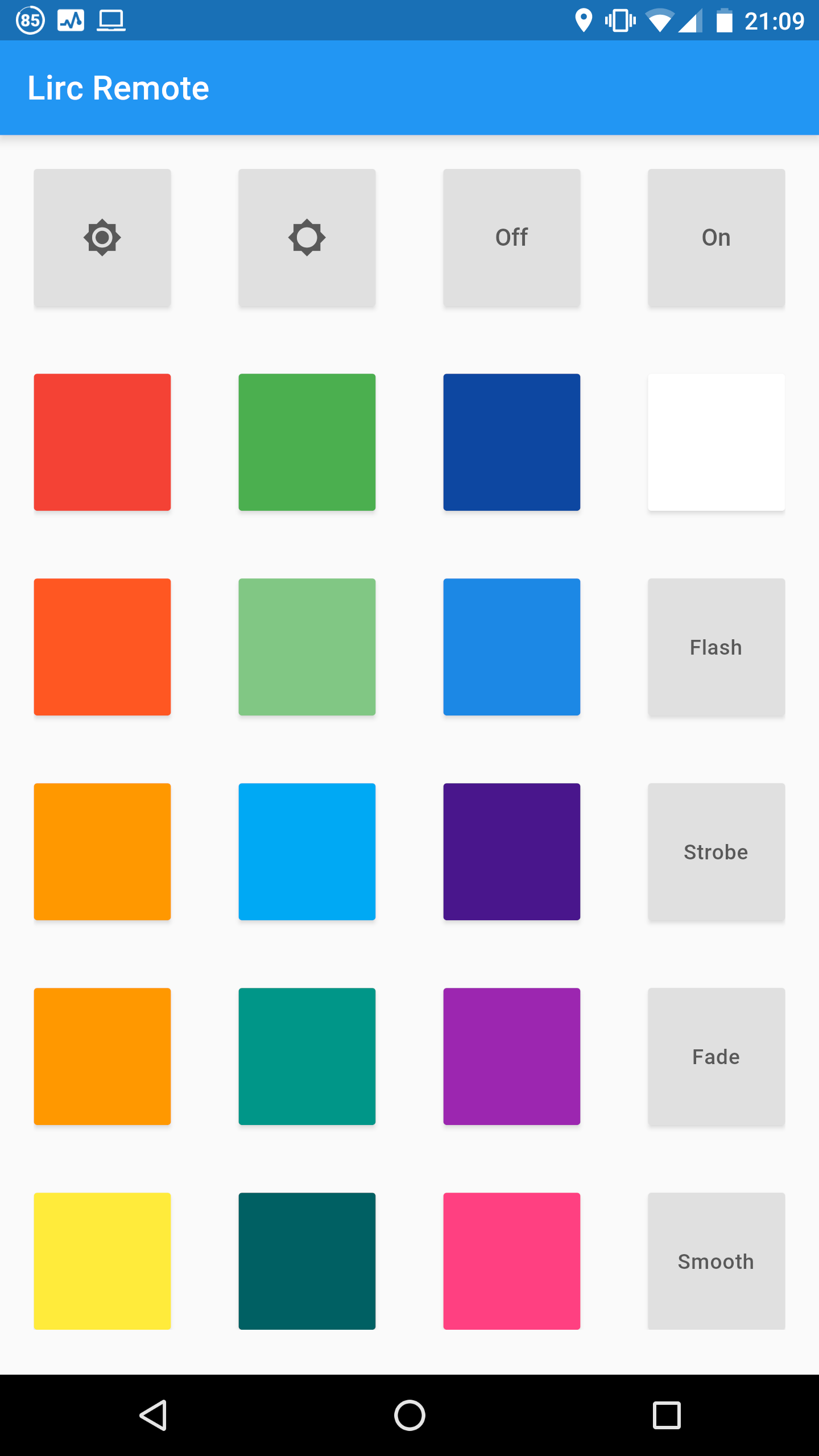
I wrote a very quick and dirty app using Flutter. I’m very ashamed of this code. I will not be sharing it until I have made it look sane. Put it this way, at the moment each button calls a different method. Not the same method with different arguments, different methods with different names like so:
void _sendBrightnessUp() {
  setState(() {
    LircClient.sendCommand(address,port,"AURAGLOW brightness_up");
  });
}
Then the button itself:
new RaisedButton(
  child: new Icon(Icons.brightness_high),
  onPressed: _sendBrightnessUp,
)
Disturbing, no?
I couldn’t for the life of me figure out how to generalise that function to a general string, since onPressed requires a function with no arguments; I’m very clearly missing a trick here. But I wrote this at 2am, and clearly, didn’t care, I wanted to be able to turn the lights off and go to bed. Rather, go to bed and turn the lights off from my phone.
The secret with sending packets of data like this turned out to be DatagramSockets; Android doesn’t like to let you open a TCP/UDP socket and just leave it open for you to use later.
Anyway, here’s a screenshot:
All in all, I think this is a horrid, hacky way to it. If there’s any home automation people reading this, they’re deffo gesticulating furiously.